
From a shaft concept to a parametric Onshape model
One pipeline for every construction: describe the layers, check the tolerances, set the segments along the shaft, and generate an editable model in your own Onshape account.
Targets
OD ceiling, lumens and the segments the shaft needs from proximal to distal.
Layer stack
Liner, braid or coil, jackets, pull-wire lumens and heat shrink, each with its tolerances.
Stack-up
OD, lumen and walls by worst case, RSS and Monte Carlo, with Cp/Cpk against your limits.
Junctions
Each segment has its own stack, durometers and length; layers change where segments meet.
Onshape model
A parametric part studio: one segment with cut-back lengths, or the whole shaft end to end.
The cross-section, to scale
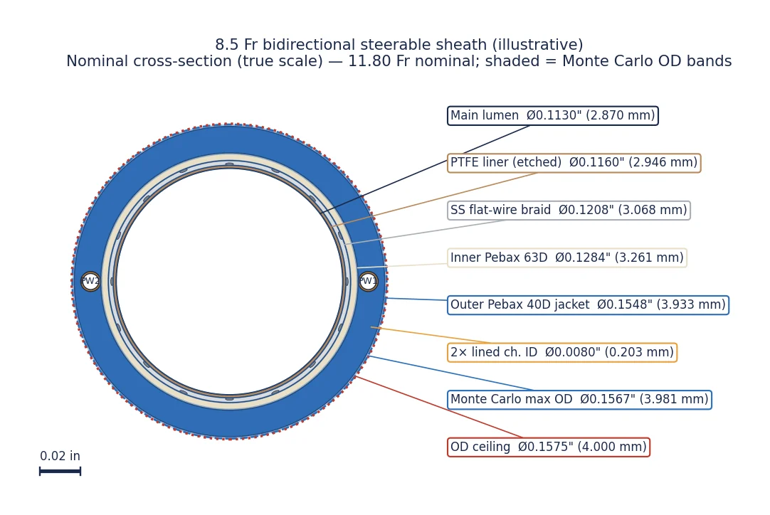
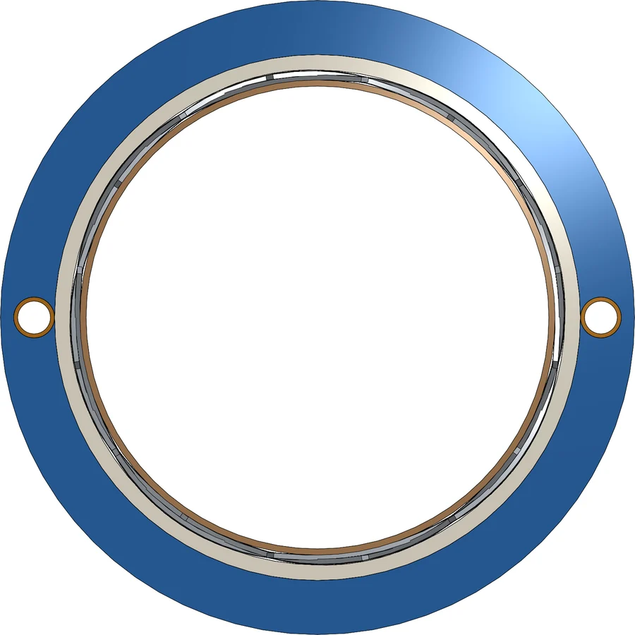
The shaft is built layer by layer, inside to out. Every layer carries its nominal and asymmetric tolerances, and the cross-section is drawn true to scale with its tolerance bands.
The spread, before you build
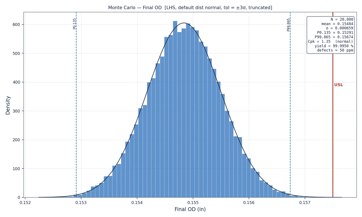
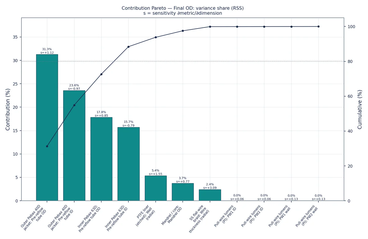
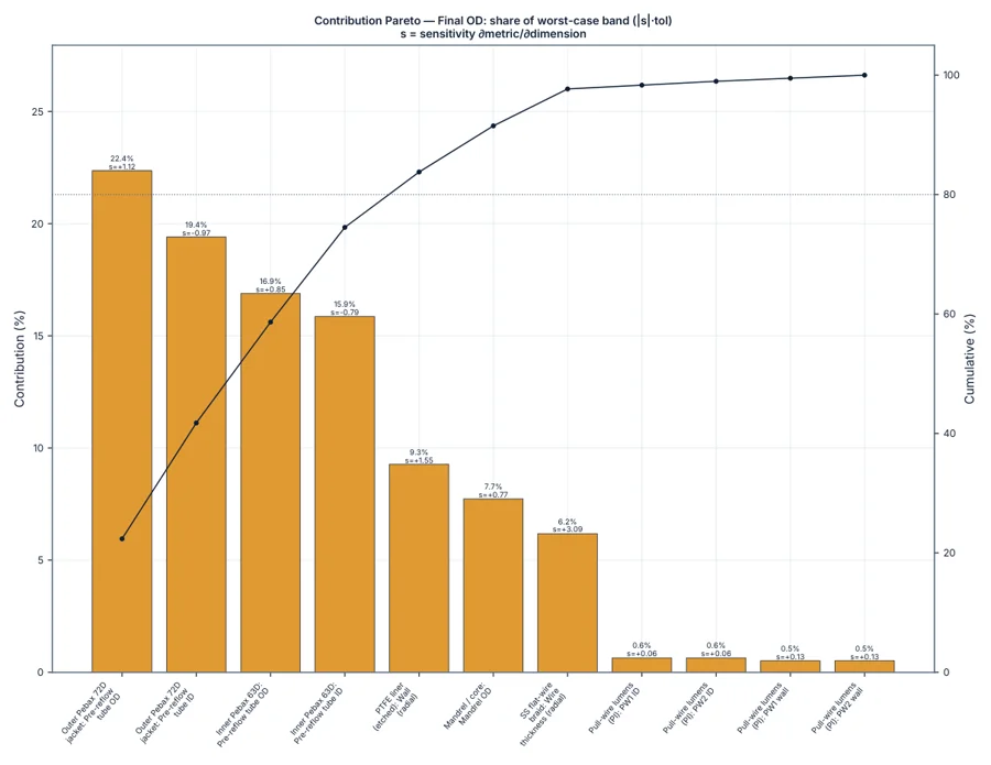
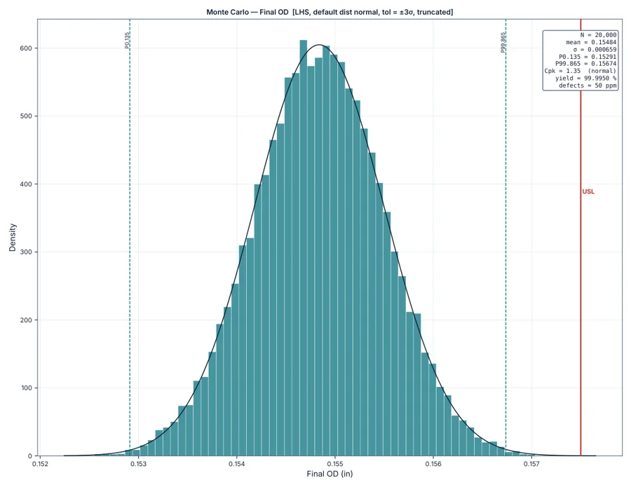
Monte Carlo shows where the OD lands against its ceiling, and the contribution Pareto shows which tolerances drive it.
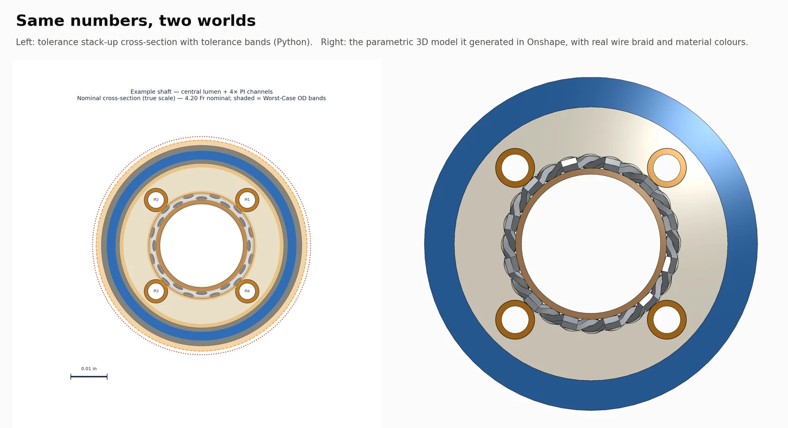
The same numbers, in Onshape
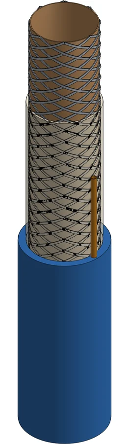
The model is generated from the design: layers, braid and coil wires, lumens and material colours, as an editable parametric part studio in your own Onshape account.
Different constructions, same pipeline
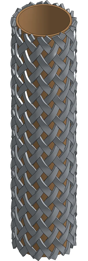
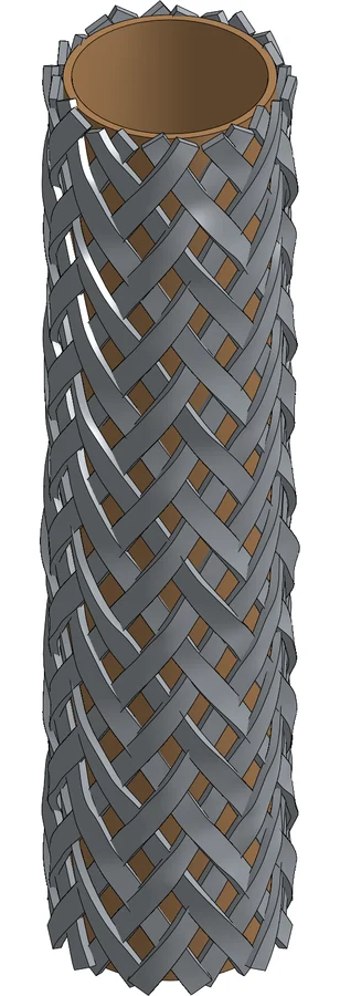
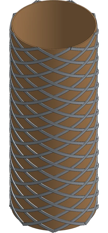
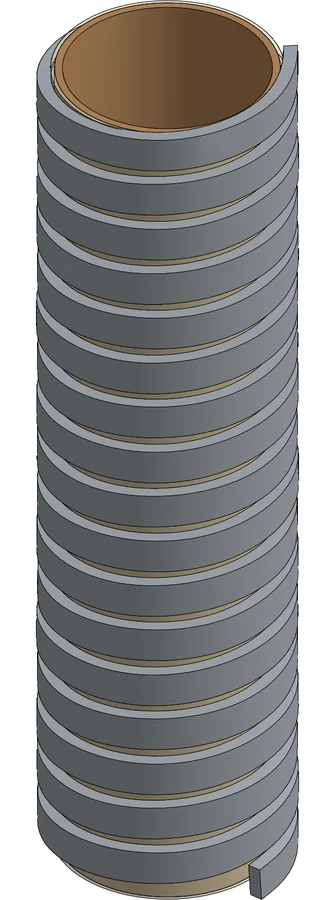
Braid pattern, wire shape and reinforcement type are part of the layer stack, and each is modelled as real geometry.
How the shaft changes along its length
A shaft is a series of segments, each with its own layer stack, durometers, lengths and limits. At a junction, the layers that continue run through and the ones that change start or stop, and the whole-shaft model places every segment end to end.
Jacket durometer change
A stiffer proximal jacket meets a softer distal one, while the liner and braid run through.
Reinforcement change
The braid ends and a coil or plain jacket takes over toward the tip.
Step in OD or lumen
The wall or a lumen steps down where the shaft narrows toward the distal end.
Charts from the analysis
The PDF a design review gets
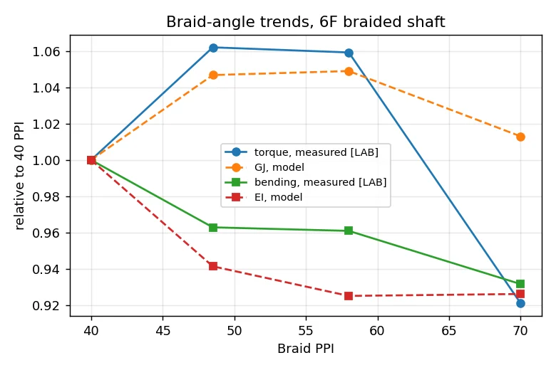
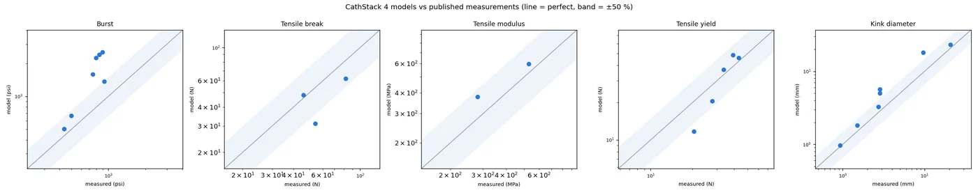
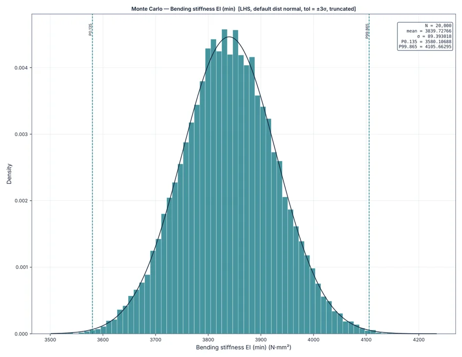
A sample report from the example sheath, exactly as CathStack exports it: inputs, checks, capability, contribution Pareto, schematics, mechanics with bands and the profile along the shaft.
See it on your own shaft
Send a construction you're working on, and we'll walk through it live.